Viewport baked PBR materials
The technique described here is very basic, but useful nonetheless.
Let’s make the following broad assumptions:
- No interactions between surfaces (i.e., no GI, no occlusion, etc…).
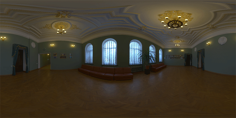
- The only light source is an IBL (environment) map placed at infinity which orientation is anchored to the camera.
- Each surface point
Pis made of a perfectly rough white material which simply “collects” the light that arrives toPfrom above the hemiplane defined by(P,N).
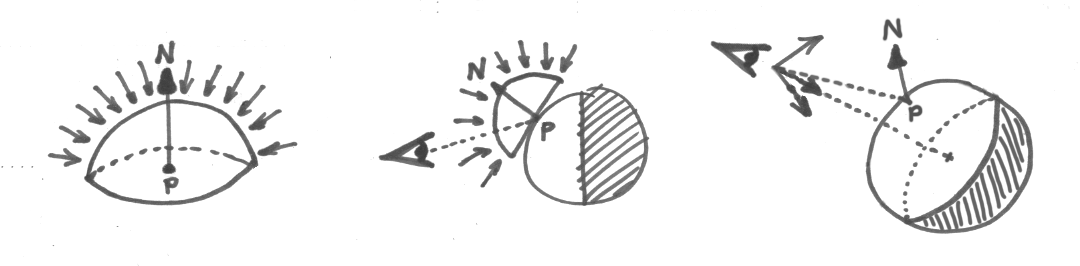
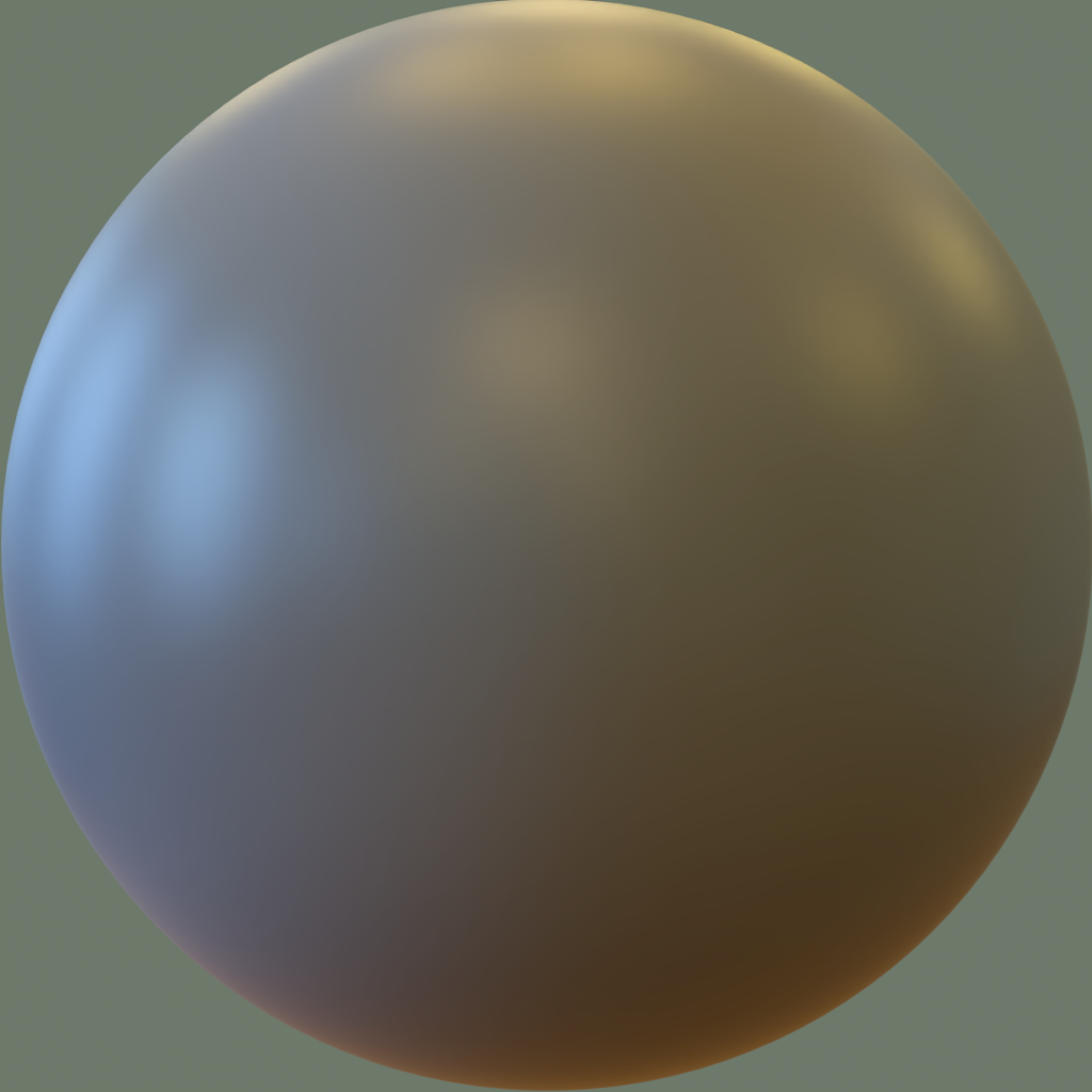
Under such assumptions a ball floating in the void looks like this image rendered in Maverick Studio with a procedural sphere primitive and a standard material:
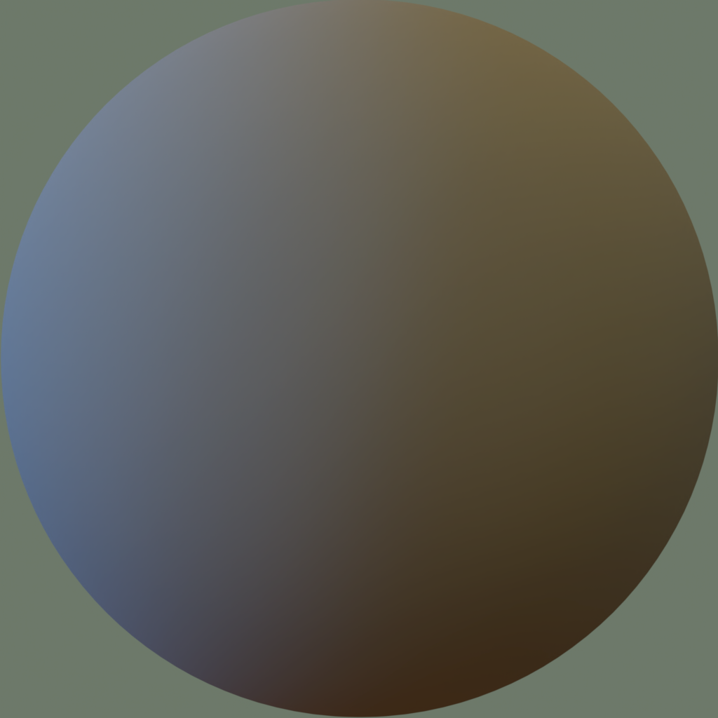
The illumination collected by each point P and radiated back to the camera (+ tonemapping) happens to be, exactly, one particular pixel in the rendered ball as depicted in the hand-drawn diagram above. Note that due to the constraints set, this color depends exclusively on the normal N at P but not on P itself. In other words, the rendered ball effectively precomputes what any surface point P sees through its normal N.
The goal in this post is to benefit from this knowledge in a rasterization viewport. So let’s jump now to the world of pixel shaders. In our vertex shader, let’s transform the object’s normals N to camera space Nc and let’s drop the resulting Z coordinate. (Nc.x,Nc.y) are the geometry normals projected to screen space. Let’s normalize these: Nc'=normalize(Nc.x,Nc.y)
Let’s upload the ball render as a regular 2D texture and let’s define the following UV space:
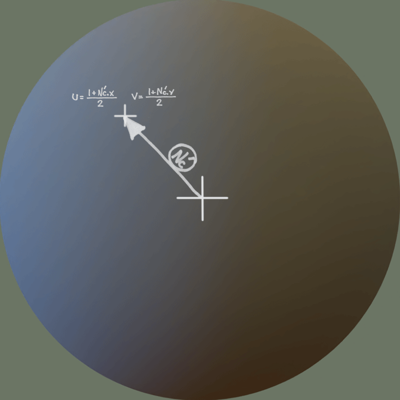
Nc' is normalized, so the UVs generated will cover the interior of the ball only. Normals at grazing angles will be near the perimeter of the texture’s ball.
In our fragment shader, let’s simply output the color found in the ball image at the UVs computed as described. Here’s the result:
Of course, physically-based materials are more complicated than this. In general, the amount of light received by the surface from the (P,N) hemiplane through each possible incoming direction and then bounced back through each possible outgoing direction depends on both directions, and also on the properties of the material. This is basically the definition of a BRDF, BTW.
But because we set the constraint that the lights are not moving (i.e., the IBL stays fixed with respect to the camera) the incoming and outgoing directions and hence the behavior of the BRDF ends up being a function of N and nothing else. So this method still works no matter what material we render the ball with (well… excluding refractions).
Here goes another example with the same IBL but adding some specularity to the material:
Of course this could be pushed further with some SSAO or any other technique that approximates self-shadowing. But this is a very compact and cheap (memory/code/effort) way to display models in an easy-to-author appealing way.
Some final notes:
- If you want to be accurate, the ball should be rendered with an orthographic camera (i.e., not with a perspective camera).
- For blurry/glossy or diffuse reflections, you can get away with a low-res ball render. However, make sure that the UVs that you generate don’t step on the antialias pixels at the boundary of the rendered ball. Otherwise shading will look b0rked at grazing angles.
- This technique can be extended by using 2 ball images: one with the diffuse component of the material, and another with the specular component. This way the fragment shader could modulate the diffuse part and the specular part by separate colors that could be passed as inputs to the shader. Keep in mind that this would require that the ball images and the colors are passed in linear (instead of sRGB) space and that the resulting color is sent back to sRGB.